Skip to content
No results
About K9SWX
About Us
Affiliate Disclaimer
Block Content Examples
Contact
Contact Us
FM DX Equipment
Homepage
Landing Page
TV DX Equipment
K9SWX
Audio Streams
K9CU 146.760-Champaign IL
K9CU 444.100-Champaign IL
NOAA Weather Radio (WXJ76) Champaign IL
Ham Radio
PSK Reporter Map (K9SWX)
wspr.rocks (K9SWX)
TV/FM DX
FM DX Equipment
Autologger – K9SWX (FM)
TV DX Equipment
Autologger (Map)
Autologger (List) (Last 24 hours)
Videos
About
Contact
Search
Ham radio | Raspberry Pi | SDR | other tech stuff
K9SWX
Menu
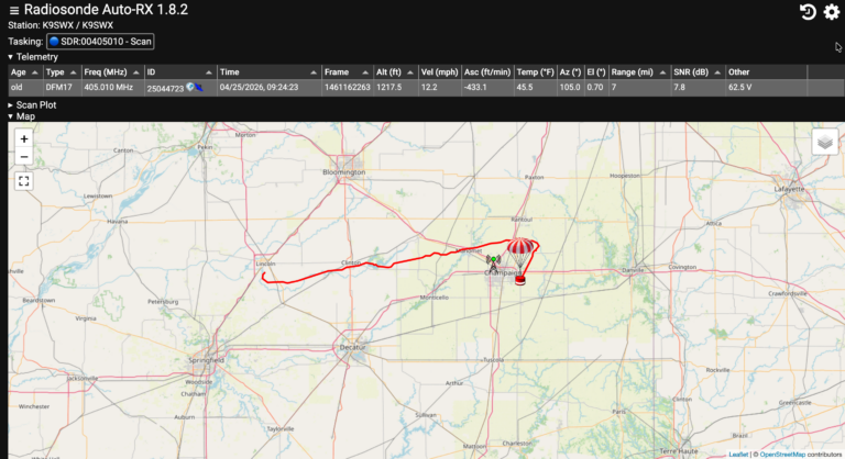
Track weather balloons with a Raspberry Pi and RTL-SDR
K9SWX
April 26, 2026
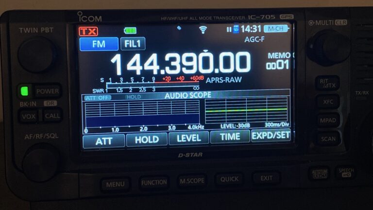
Portable APRS digipeater using an Icom 705 and Raspberry Pi
K9SWX
August 30, 2025
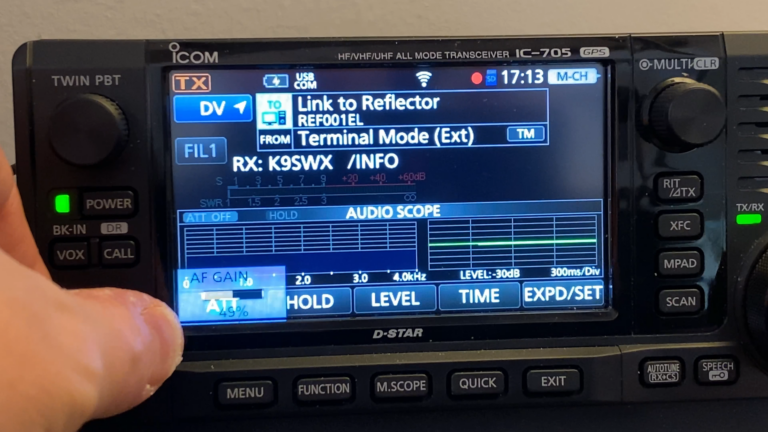
Connect to D-STAR reflectors using an Icom 705 and Raspberry Pi
K9SWX
August 31, 2024
8 Comments
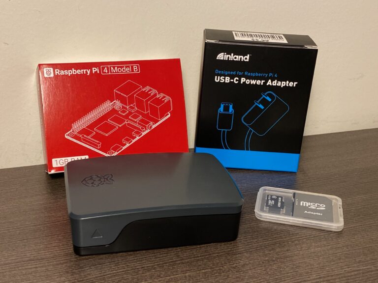
Raspberry Pi OS Lite 64-bit operating system installation tutorial
K9SWX
June 22, 2024
3 Comments
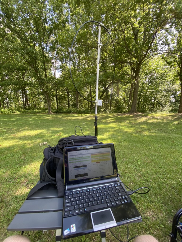
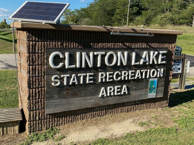
Memorial day POTA activation at Clinton Lake (US-4093)
K9SWX
June 3, 2024
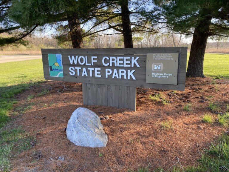
Failed POTA activation at Wolf Creek State Park (US-1033)
K9SWX
June 1, 2024
My first POTA activation at Clinton Lake (US-4093)
K9SWX
September 16, 2023
2 Comments
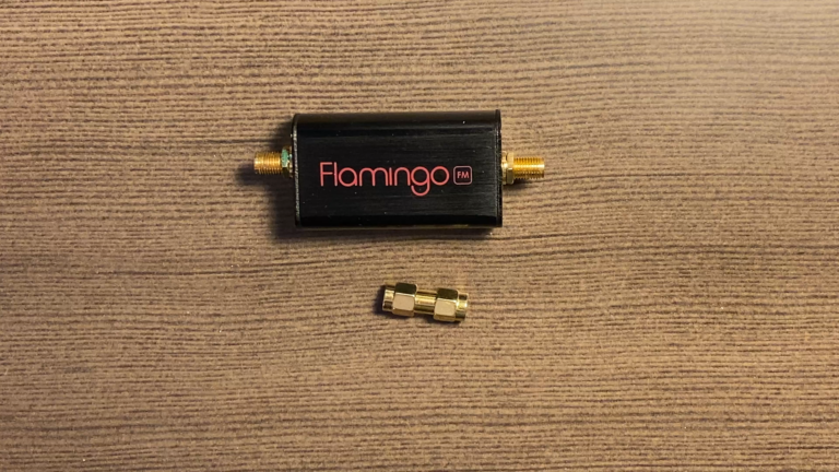
Block broadcast FM interference with an FM notch filter
K9SWX
May 27, 2023
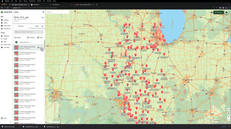
Gaia GPS and ham radio
K9SWX
May 7, 2023
Where to buy used ham radio gear
K9SWX
April 22, 2023
1
2
3
Next